
Aerobic Septic System Monitor - Part 2 - Beta Testing
The beta testing chapter is a look at each of the different components that make up the Aerobic Septic System Monitor. Each section is an exercise in connecting and programming a component. If you are new to the Arduino/ESP32 you will want to work through each section to gain a better understanding of each component attached to the ESP32. This chapter is optional and if you want to get directly to monitoring your aerobic septic system you can jump to “v1.0 The Basics”.
Blink (ESP32)
If you are new to the Arduino/ESP32 world, blink is the classic “Hello World!” program for the Arduino developer. This exercise involves using the build-in LED on pin 13 of many Arduino boards or wiring to an LED to an one of the many digital pins with a 220 ohm ballast resistor to limit the current flow. Since the ESP development board does not have a built-in LED I used the following wiring example.
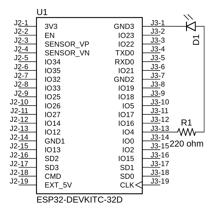
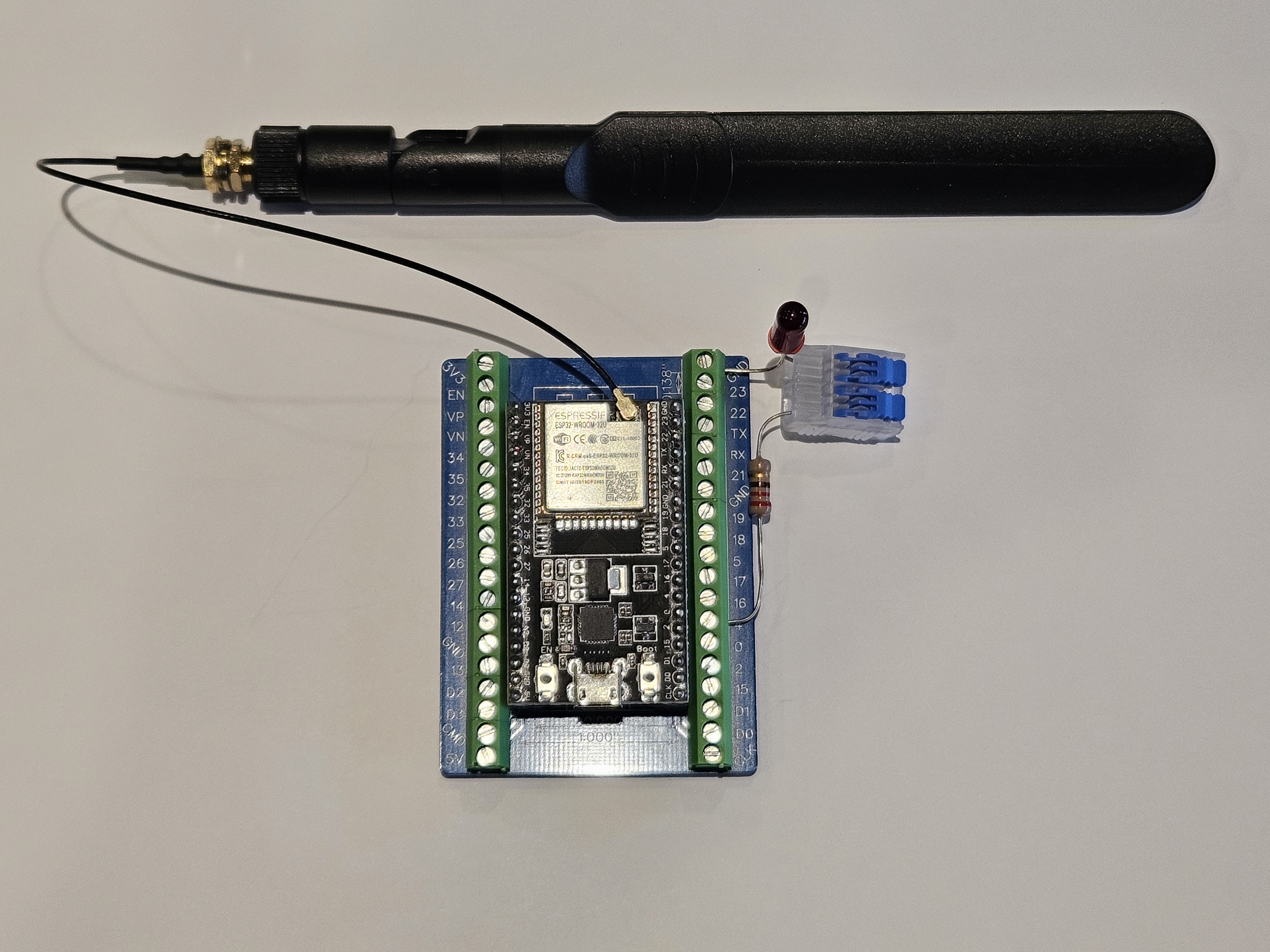
I my case, I used the breakout board and an Ideal Lever Wire Connector to connect the LED and 220 ohm resistor without the need to solder.
| ESP32 | LED | 220 ohm Resistor |
|---|---|---|
| GND (-) | Cathode (-) | |
| Anode (+) | Lead | |
| GPIO 4 | Opposite Lead |
The blink sketch is included in this project in the folder labeled /Blink. With the ESP32 Development Board I chose there is no built in LED so I had to manually redefine the LED_BUILTIN constant in the code. In my case I used pin 4. If you are new to programming an Arduino/ESP32 I recommend starting by reading “Getting Started with Arduino IDE 2”. You can also search the internet for “Arduino blink” or “programming the Arduino” to find a great deal of articles and tutorials.
Beyond Blink (ESP32)
Beyond Blink is an exercise to look at the simplicity and power the ESP32 has when it comes to connecting to your Wi-Fi network and the Internet. The code was adapted from the Last Minute Engineers - Learn Electronics the Easy Way article In-depth: Create A Simple ESP32 Web Server In Arduino IDE (lastminuteengineers.com) and demonstrated how to connect your ESP32 to a Wi-Fi network hosing a web page that presents a button that can be used to turn the LED on and off.
This exercise uses the same wired LED from the Blink exercise. You will again need to edit the code to modify LED_BUILTIN if you are using a pin other than 4 for the LED. You will also need to edit the configuration.h header file to add your Wi-Fi SSID and password. The code can be found in the /BeyondBlink folder.
Is the Power On (220V Optocoupler Module)
As part of this project I need to be able to see if the power is on. In particular, I want to monitor the pump timer, the air compressor pump timer, the high water alarm and the air compressor alarm.
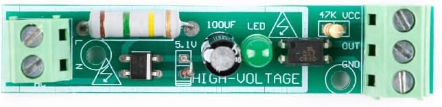
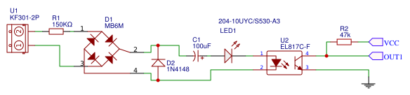
To do this I will use a simple 220V optocoupler module (pictured above) which can be connected to the hot 120V lead (‘L’ for load, typically a black wire) of any of the items I previously listed and common (‘N’ for neutral, typically a white wire) on one side of the module. On the other side I connect the module to 3.3 voltage (VCC - positive voltage), ground (GND - ground, negative) and one of the GPOI (General-Purpose Input-Output) pins of the ESP32 (OUT - signal). You can learn more about the ESP32 GPOI pins at ESP32 Pinout Reference: Which GPIO pins should you use? - Random Nerd Tutorials. Below is a diagram for a test circuit.
| 220V Optocoupler Module | ESP32 |
|---|---|
| VCC | 3V3 (+3.3V) |
| GND | GND (-) |
| OUT (signal) | GPIO 34 |

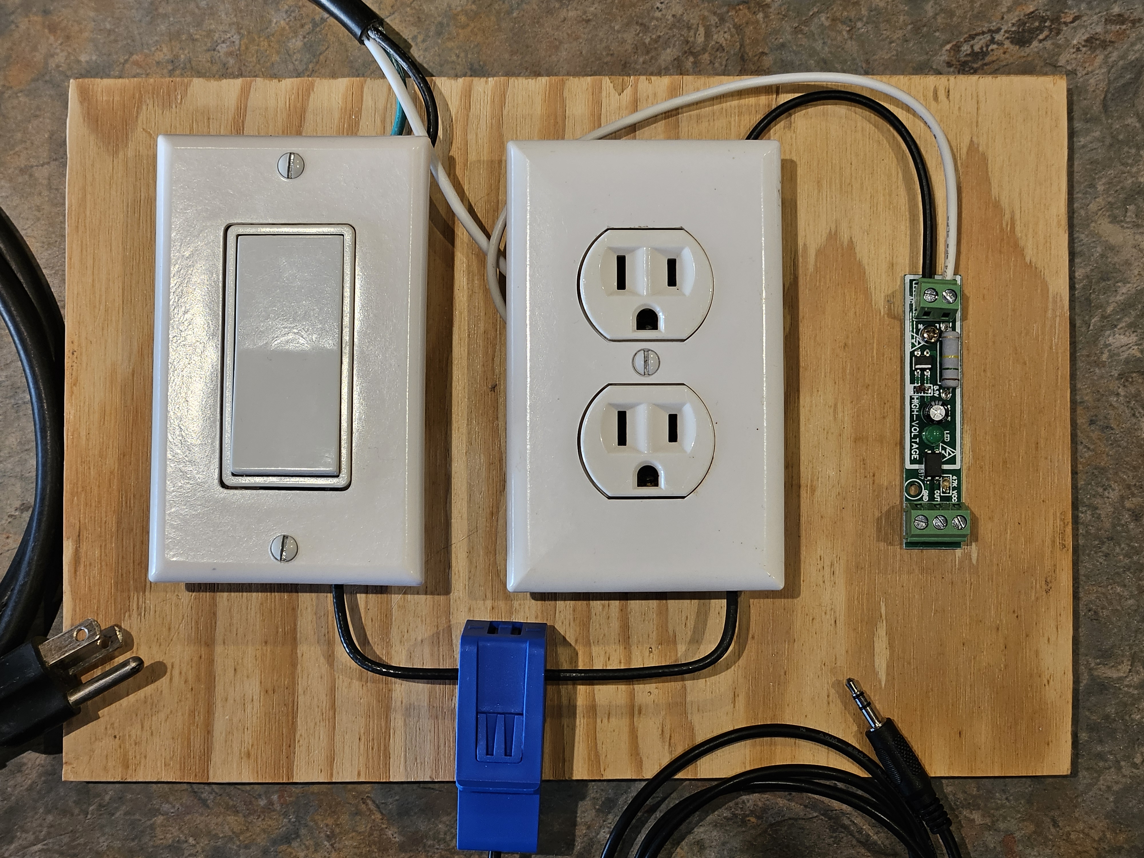
The following is a photo of the AC circuit test board I built for testing based on the test circuit above. When plugged in and the the switch is on, the plug has power and the optocoupler module (green PCB (Printed Circuit Board), far right of photo) will sense voltage. In the next module I will discuss the current sensor (blue PCB, bottom of photo).
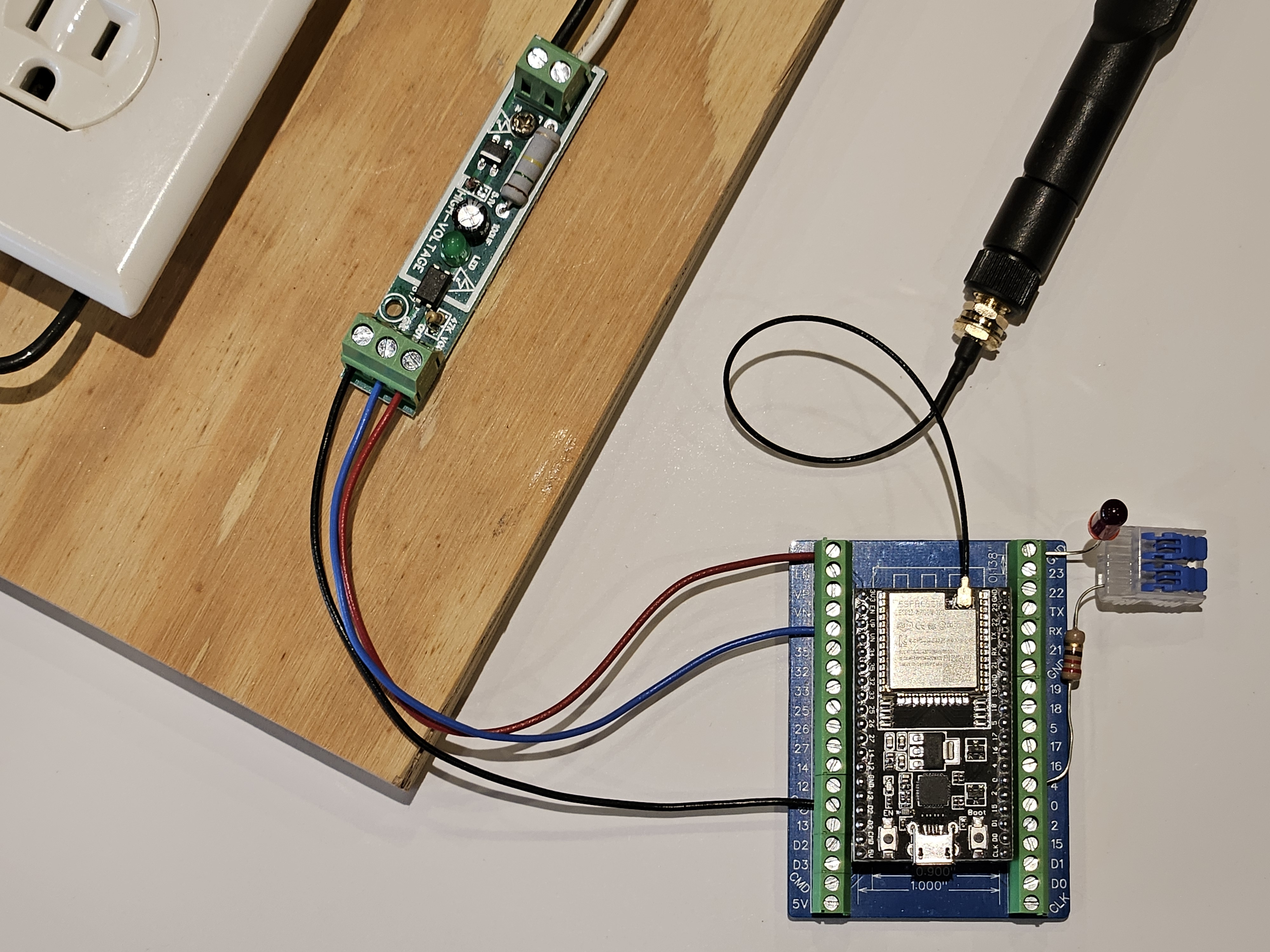
The code can be found in the /IsThePowerOn folder and is extremely simplistic. Basically when power is sensed the LED I wired in the previous exercises is turned on and a message is sent to the serial port. As before you will need to change the LED_BUILTIN constant if you use a pin other than GPIO 4. You will also need to change the POWER_ON_OPTOCOUPLER_MODULE constant if you use a GPIO pin other than 34. In the photo below VCC on the optocoupler is wired to 3V3, OUT to GPIO pin 34 and GND to GND on the development breakout board.
Is the Pump Running (Current Sensor)
While determining if the pump has been turned on by either the pump timer or the high water override float is a simple mater of using a 220V optocoupler module to detect voltage, I can’t always be certain that the pump is running since a low water float is tied directly to the pump circuit after the control box wiring. The low water float is wired in to the circuit to keep the pump from running and possibly burning out when there is no water in the septic clear water tank.
Now I could loop back a wire from the low water float/pump connection and wire it to a 220V optocoupler module to determine if the pump was running, but depending on the distance of the control box from the pump this could be extremely difficult. Also, since the low water float is most likely wired directly to one of the pump leads, it is also most likely connected with a special water proof heat shrink connector which complicates things, and making this project more complicated is not an objective.
.jpg)
Using a current sensor that can be easily clipped around the power lead leaving the control box is much easier. For this reason I chose the Gravity 20A Analog AC Current Sensor from DFRobot. I did originally look at using a cheaper current sensor based on the ZMCT103C, but after several hours of trying to get a reading, the fact that it had a 5A maximum, requires 5V to power and did not easily clip on to a wire I moved on to this sensor.
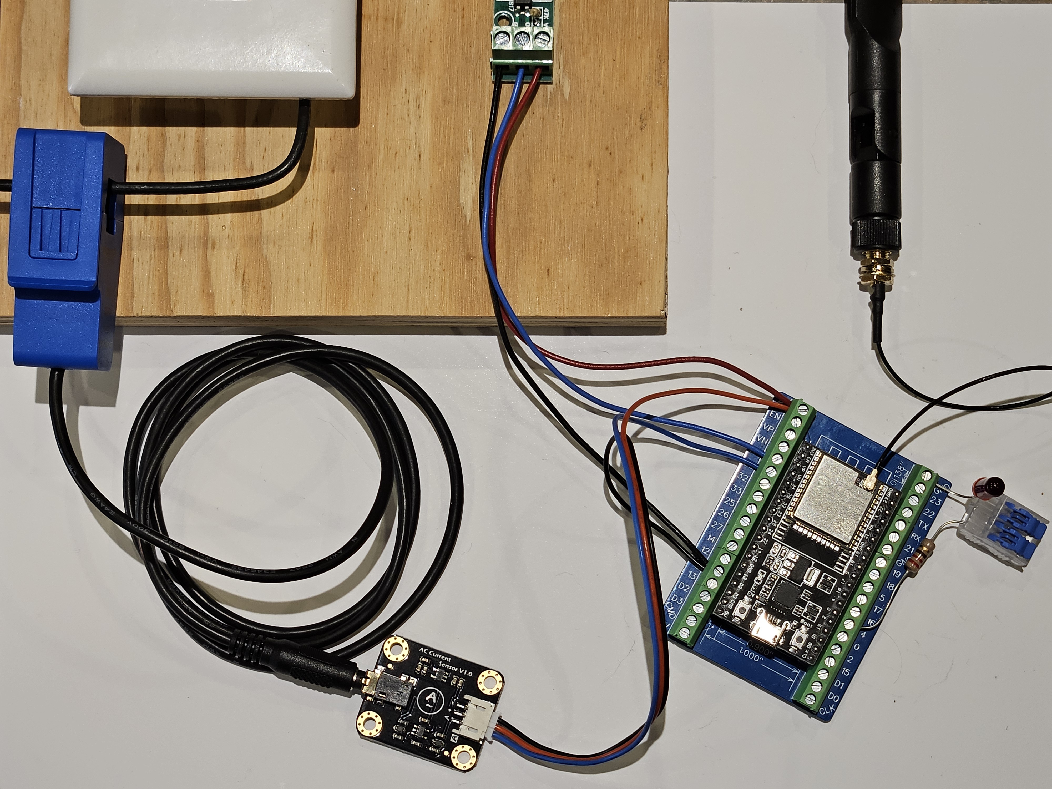
The DFRobot current sensor is easy to clip on to a wire, connect to the ESP32 and the example code was easy to implement with only one hitch discovering that the ESP32 12 bit analog requires you divide by 4096 verses 1024. In the photo below the sensor is connect with the positive lead (+) connected to the ESP32 3.3V (3V3), the negative lead (-) to ground (GND), the signal (A) connected to GPIO pin 35 and the AC transformer probe clipped on to one power lead.
| Gravity 20A Analog AC Current Sensor from DFRobot | ESP32 |
|---|---|
| + (positive) | 3V3 (+3.3V) |
| - (negative) | GND |
| A (Amperage signal) | GPIO 35 |
The code can be found in the /IsThePumpRunning folder and is based off of the vendors example code. The LED will blink to indicate activity and the amperage will be displayed on the serial port about once every second. As before you will need to change the LED_BUILTIN constant if you use a pin other than GPIO 4. You will also need to change the AC_CURRENT_SENSOR constant if you us a GPIO pin other than 35.
Where is my Data (SD Card Reader)
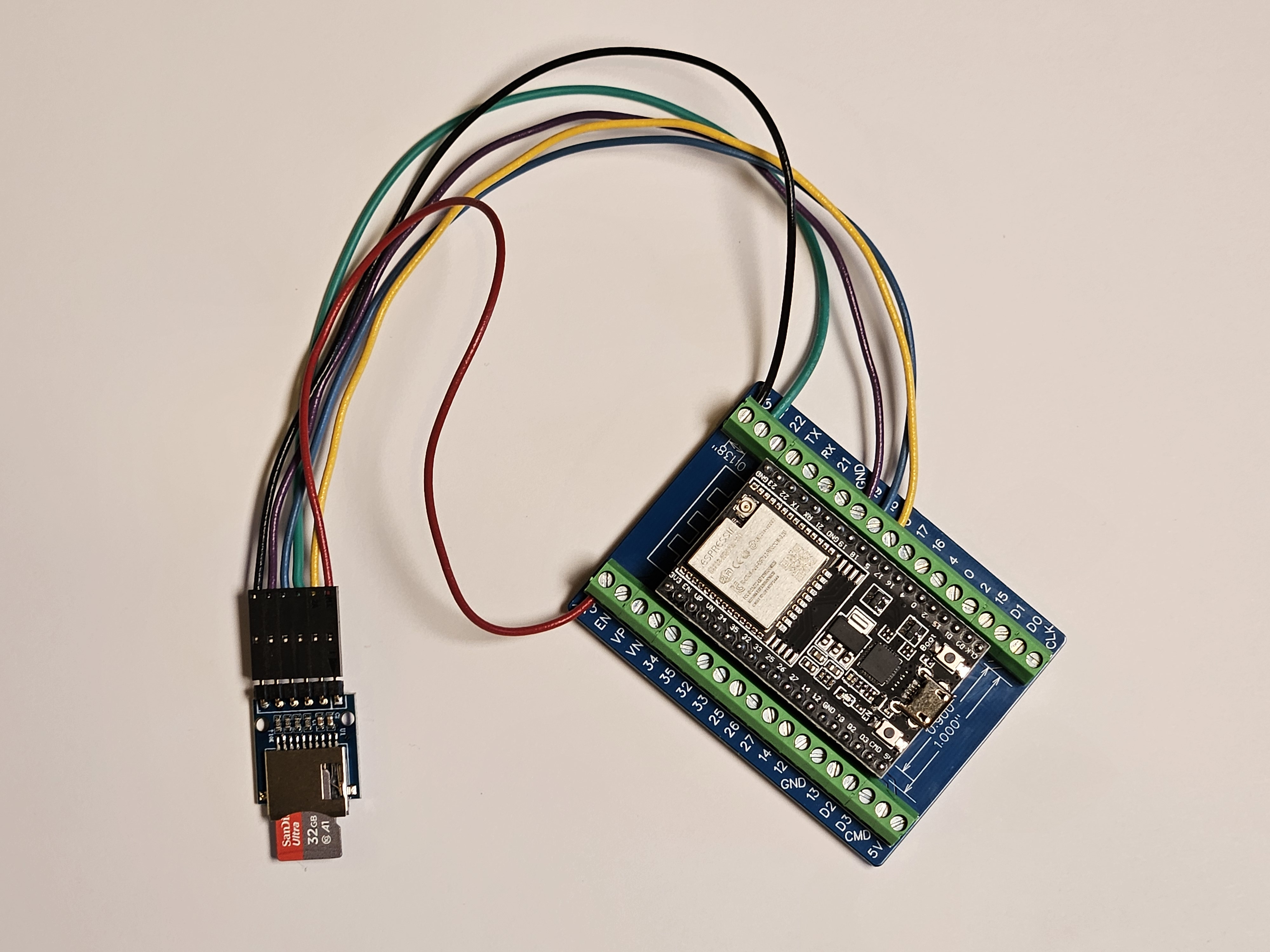
Later in this project I will look at logging data. To do this I will use an SD card. SD cards can store large amounts of data in a file format that can be read by any personal computer. The SD card reader I chose to use is operated on 3.3V and you should note the description on Amazon is incorrect about it operating on 5V. You will find other SD card reader modules that work on 5V which are compatible with 3.3V inputs. I simple chose the 3.3V version to stock my workbench with modules I could use with future ESP32 projects that might run off of batteries.
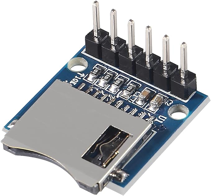
The SD card reader module communicates using SPI communication protocol. You can connect it to the ESP32 using the default SPI pins.
| SD Card Reader | ESP32 |
|---|---|
| 3V3 | 3V3 (+3.3V) |
| GND | GND (-) |
| CS | GPIO 5 |
| MOSI | GPIO 23 |
| CLK | GPIO 18 |
| MISO | GPIO 19 |
To test the module you will first want to format the micro SD card using your personal computer. Most laptops have an SD card slot you can use with an micro SD card adaptor or you may need to purchase a USB SD card reader. On a Windows machine you will open file manager, select the card and format it as FAT32.
The test code can be found in the /WhereIsMyData folder and is pulled from the ESP32 SD example code SD_Test with the SD_CS set to GPIO pin 5. The following are two good tutorials on using SD card readers with the ESP32.
ESP32: Guide for MicroSD Card Module Arduino - Random Nerd Tutorials
In-Depth Tutorial to Interface Micro SD Card Module with Arduino (lastminuteengineers.com)
What Time is It? (RTS DS3231)
As part of data logging and determining if the pump timer is correctly set, I need to know what time it is. To do this I will use a real-time clock module (RTC) with the DS3231 RTC chip and an AT24C32 EEPROM chip.
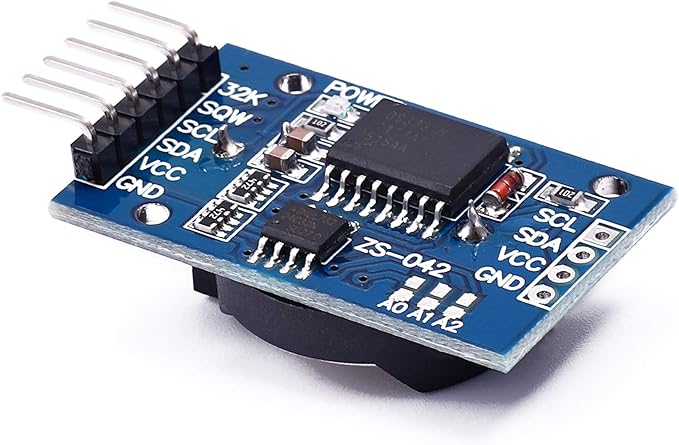
The RTC module communicates using the I2C interface for which the ESP32 has two build in IC2 controllers. The DS3231S RTC chip’s fixed I2C address is 0x68.
| RTC module | ESP32 |
|---|---|
| GND | GND (-) |
| 3V3 | 3V3 (+3.3V) |
| SDA | GPIO 21 (I2C SDA) |
| SCL | GPIO 22 (I2C SCL) |
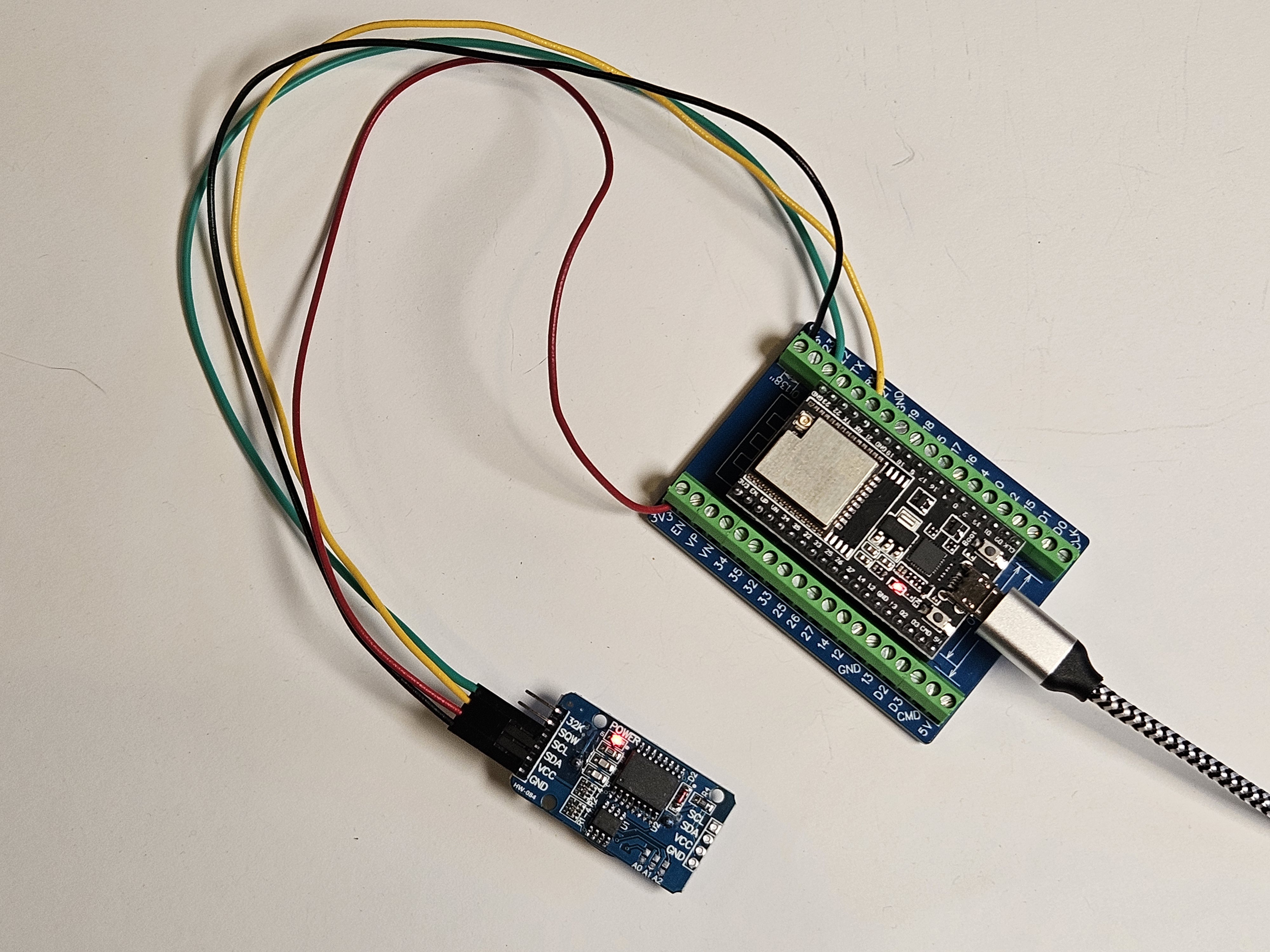
The test code can be found in the /WhatTimeIsIt folder and is pulled from the article In-Depth: Interface DS3231 Precision RTC Module with Arduino (lastminuteengineers.com). You will also need to load the uRTCLib by Naguissa library. The code can be used to set the chips time and then display the current time. Read the comments in the code for setting the current time.
Don’t Let Me Forget (AT24C32)
One of the nice things about the real-time clock module (RTC) is that in addition to the DS3231 RTC chip, it also has an AT24C32 EEPROM chip which can hold 32K of information even when the power is off. For this project I will use this memory to store settings like, during what time should the pump be on, the Wi-Fi SSID and password and user names, passwords and roles.
The test code can be found in the /DontLetMeForget folder and is also pulled from the article In-Depth: Interface DS3231 Precision RTC Module with Arduino (lastminuteengineers.com). You will also need to load the uEEPROMLib by Naguissa library. The code writes an integer, float, character, and string to the 24C32 EEPROM and then reads them back.
Show Me (OLED Display)
The last module to look at is an SSD1306 OLED 0.96 inch display with 128×64 pixels with an I2C interface. This module can be optional, but I added it because I’m not worked with one of these and I thought it would be useful to have some local visual feedback.
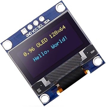
Just like the RTC and EEPROM the display connects through the I2C interface. One thing to note is that while the silk screen printing on the back of the module indicates an I2C address of 0x78, the correct address 0x3C.
| OLED module | ESP32 |
|---|---|
| GND | GND (-) |
| VCC | 3V3 (+3.3V) |
| SCL | GPIO 22 (I2C SCL) |
| SDA | GPIO 21 (I2C SDA) |
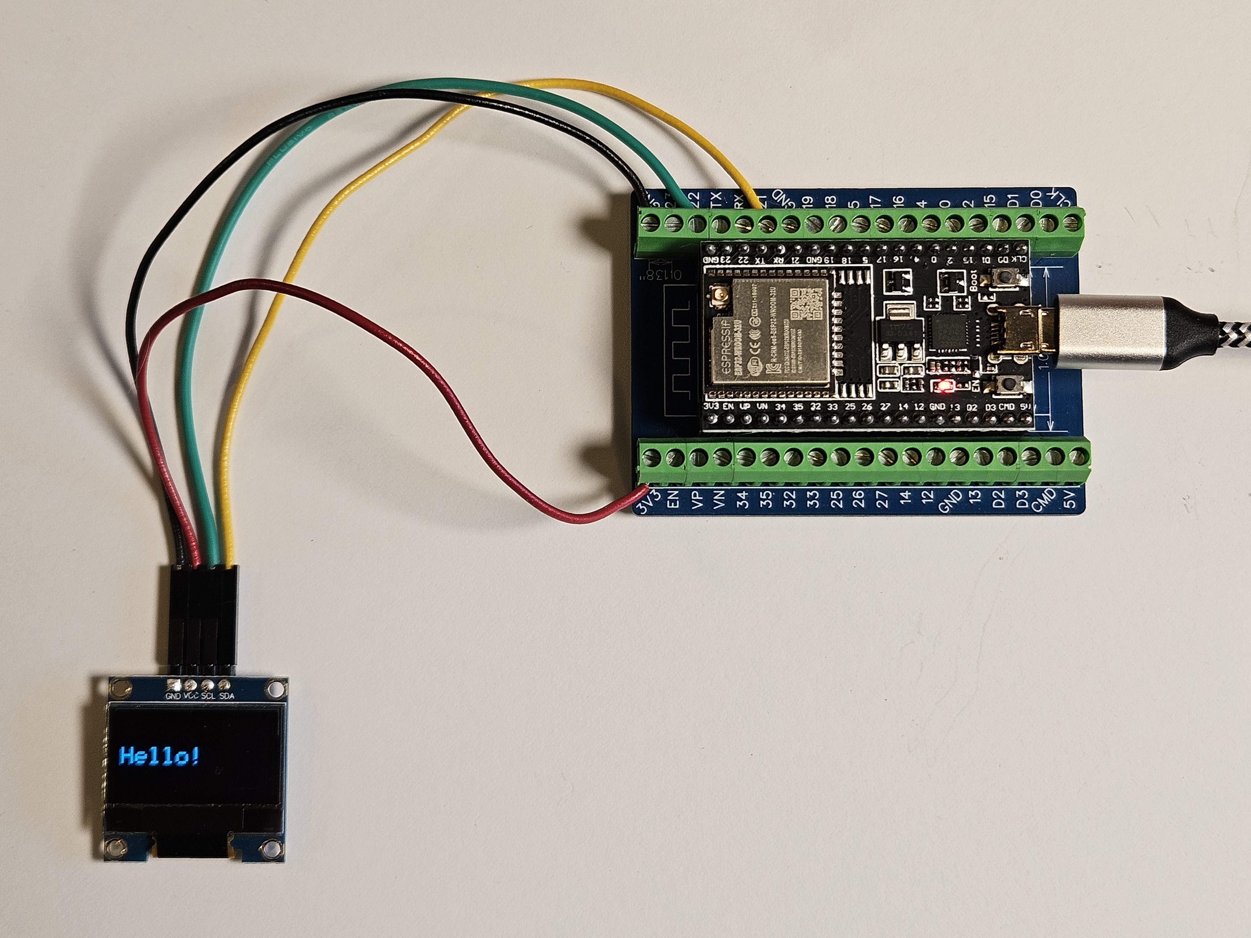
The test code can be found in the /ShowMe folder and is pulled from the article In-Depth: Interface OLED Graphic Display Module with Arduino (lastminuteengineers.com). You will also need to load the Adafruit SSD1306, Adafruit GFX, and Adafruit Bus IO libraries. The code displays various different text messages on the display. You can find additional examples in the article ESP32 OLED Display with Arduino IDE - Random Nerd Tutorials.
More to Come…
If you can’t wait for the next article “v1.0 The Basics”, you can get a sneak peek at the GitHub repository.